Baltimore sits at the transition between the Atlantic Coastal Plain and the Piedmont Plateau. The city’s subsurface is dominated by saprolite—weathered mica schist and phyllite—that can exhibit rapid strength loss when exposed to water or excavation. This makes slope stabilization design in Baltimore a geotechnical challenge that demands site-specific shear strength parameters and groundwater modeling. Shallow groundwater within the Inner Harbor fill zones further complicates stability for cuts deeper than 3 meters. Before finalizing a stabilization plan, it is common to run a dilatometer test to obtain in-situ lateral stress and stiffness data, or to verify the foundation response with a plate load test when the slope supports a structure.
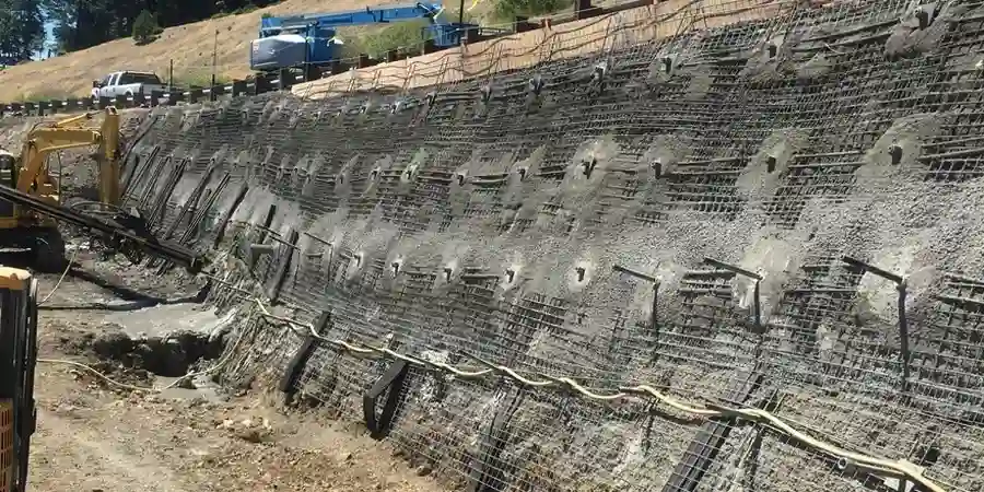
Weathered Piedmont saprolite can lose 50% of its shear strength within hours of exposure—slope stabilization design in Baltimore must account for this rapid degradation.
Method and coverage
- Subsurface logging per ASTM D1586 with SPT blow counts correlated to residual soil strength.
- Laboratory direct shear and triaxial testing on undisturbed block samples from test pits.
- Limit-equilibrium and finite-element modeling with Slide2 or Plaxis 2D.
Regional considerations
The humid summers of Baltimore cause rapid infiltration into the residual soil mantle. After a heavy storm, the phreatic surface can rise 1.5 m in 24 hours, reducing effective stress and triggering shallow translational slides. Combined with the high plasticity index (PI 25-40) of the clay-rich B-horizon, this creates a classic scenario for progressive failure. A slope stabilization design in Baltimore that ignores transient seepage analysis will likely underestimate long-term creep. The city also lies in Seismic Design Category B (ASCE 7), so pseudostatic slope checks are mandatory for any cut exceeding 6 m adjacent to existing structures.
Standards that apply
ASCE 7-22 (Seismic load and site class), IBC 2021 (Chapter 18 – Excavation and grading), FHWA-NHI-05-089 (Soil nail walls and slope stability)
Related services
Reinforced Soil Slopes (RSS) & Geosynthetic Design
Design of wrapped-face or modular-block reinforced slopes using geogrids or high-strength woven geotextiles. Suitable for highway embankments along I-83 or I-95 where right-of-way is limited. Includes internal and external stability checks per FHWA.
Soil Nail Wall & Anchor Systems
Temporary or permanent soil nail walls for cuts up to 10 m. We design the nail pattern, grout bond length, and facing thickness based on the saprolite's friction angle. Corrosion protection per IBC for permanent installations.
Typical parameters
Common questions
When is a slope stabilization design required in Baltimore?
Any cut or fill exceeding 1.8 m (6 ft) in height that is within 3 m of a property line or existing structure requires a geotechnical report with slope stability analysis per IBC 2021. The Baltimore City Department of Housing & Community Development enforces this during permit review.
What is the typical cost range for slope stabilization design in Baltimore?
For a residential lot with a single cut slope up to 6 m, the engineering and testing scope ranges between US$1.490 and US$7.000. Complex projects with multiple tiers, groundwater control, or tieback anchors fall at the upper end.
How does Piedmont saprolite affect stabilization design?
Saprolite retains the relict structure of the parent rock, creating weak bedding planes that can daylight into the excavation face. It also softens rapidly when saturated. We use residual friction angles from ring-shear tests on remolded samples to model the long-term drained condition.
Do you include groundwater monitoring in the design?
Yes. We install standpipes or vibrating-wire piezometers during the site investigation and monitor for at least one month through a wet season if possible. The measured phreatic surface is then used directly in the stability model.
What is the minimum factor of safety required by local code?
The Baltimore City code references IBC 2021, which stipulates a minimum factor of safety of 1.5 for static conditions and 1.1 for pseudostatic (seismic) conditions. For critical infrastructure such as bridge abutments, we often target 1.3 to 1.4 under seismic loading.